 MC Grating
Layers
This documentation was written for releases up to 2018 and is being revised. Some dialogs have changed since. If something does not match what you see, write to mc@mcgrating.com.
- The incidence always takes place from the cover medium and the layers are enumerated from the cover to substrate medium. If the user wants to illuminate the structure from the substrate medium, the role of cover and substrate must be swapped. Button C-S swaps the role of cover and substrate and reverses the order of the layers inclusive of the grating.
- The elementary grating cell of each layer of given Layer index and given Thickness may contain more than one cylindrical pillars of identical height. The user can edit the pillars parameters individually. The N Pillars and Index controls define the number of pillars and the pillar index for edit controls in the panel at the right. If the user wants to increase N Pillars, the software duplicates the pillar with the higher index, so at this stage the user will not see any difference in the layer plot. For the insertion of the different pillar the user has to edit the parameters (X- and Y-coordinates and/or refractive index) of the last (duplicated) or previous pillar. Note that the pillar with the higher index overrides all pillars of lower index in case of pillars intersection.
- There are two possible pillar shapes. For P Points equals to two the pillar is a cylinder with an ellipse cross-section inscribed into appropriate rectangle. In the case of P Points greater than two the pillar has a polygon cross-section. The user may set the diagonal coordinates of the ellipse rectangle or polygon point coordinates by using Index and X and Y controls. The coordinate measurement unit is defined by Pillar Units control.
If the Fraction of Period of Pillar Units control is selected the user can edit pillar coordinates under following constrains
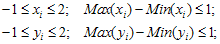
If the another Pillar Units control is selected constrains are multiplied by an appropriate factor. The pillar will be automatically inscribed in a single X-Y periods cell. - If the Pillar Plot control is checked the layer pillars structure is illustrated in separate graphic window.
- By clicking the right mouse button at Layer control the user activates the Popup Menu for editing the whole layer (copy, paste, etc.).
- This page contains the “Material” control. If any of edit field corresponding to the medium is focused, by clicking this control the user can access the Material Catalog though the Material Dialog window. If a medium is assigned with a Material the “Material” control caption indicates the Material name and the software will always take a refractive index of this Material for a current value of wavelength otherwise the “Material” control caption is “Select Material” and medium refractive index will be fixed for all wavelengths.
- By clicking the right mouse button at the “Material” control the user activates the Popup Menu which helps to manipulate with the already set materials bypassing the Material Dialog window.
- Other fields are obvious. It is necessary to emphasize the useful property of the Permittivity and Refractive index fields: after exiting from any field or after pressing the Enter key, all other fields in a line will be automatically recalculated.
Note 1 Every layer grating cell is defined in FFT grid. Pillars coordinates take values corresponding to the FFT grid nodes. FFT grid size depends on maximum Number of Orders (General page) and indicated in Pillar Units control.
Note 2 Modeling 1D grating can only be carried out by pillars in the form of parallelepipeds along the X, Y axes or at an angle of 45 degrees. In the latter case, the period should be increased to the root of 2 times.
Note 3 The imagine part positive sign of the Permittivity and Refractive index corresponds to the dissipative media while the negative sign corresponds to the media with amplification.
From the in-application help of Modal Crossed, documented through 2018. If you publish results computed with MC Grating, see how to cite it.